Spin Torque Nano-Oscillators
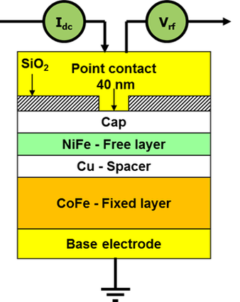
Spin Torque Nano-Oscillators (STNOs) are a new class of nano-scopic microwave oscillators with ultrawide operating frequency ranges, ultrahigh modulation rates, and manufacturing processes compatible with RF CMOS in e.g. the same way as Magnetoresistive Random Access Memory (MRAM). STNOs utilize a number of spintronic and nanomagnetic phenomena for their operation, such as spin transfer torque (STT), giant magnetoresistance (GMR), tunneling magnetoresistance (TMR), and various spin wave modes. To the left we show a typical nano-contact STNO. The active layer is a permalloy (NiFe) thin film, typically between 2 and 5 nm thick, in which a spin wave resonance is excited by a high current density injected through a nano-contact, with a typical diameter from 40 to 400 nm. The fixed CoFe layer is substantially thicker, typically about 10 to 20 nm and has two purposes. First, it provides STT to the NiFe layer through reflection of electrons at the Cu/CoFe interface. Electrons that reflect at this interface will be preferentially spin polarized in a direction opposite that of the spin polarization in the CoFe layer and in the typical case of the NiFe and the CoFe experiencing the same large external magnetic field, the spin polarization of the reflected electrons will also be opposite the spin polarization in the NiFe. When these spins impinge back onto the NiFe/Cu interface, they tend to destabilize the magnetization, and if the current density is high enough, the magnetization can be entirely destabilized and begin to auto-oscillate at the lowest energy spin wave mode. This spin wave mode initially grows exponentially in amplitude until a new equilibrium steady auto-oscillating state is reached. This steady state is characterized by a large spin wave amplitude at typically a single frequency set by the applied field strength and the current density. The second purpose of the CoFe layer is now to provide GMR together with the NiFe layer. Since the NiFe magnetization oscillates at a particular frequency, the resistance of the NiFe/Cu/CoFe trialayer also oscillates at this frequency. Consequently, the direct current and the oscillating resistance together created a microwave voltage across the STNO.
For recent good reviews about STNOs please see e.g.:
[1] T. Silva, and W. Rippard, "Developments in nano-oscillators based upon spin-transfer point-contact devices." J. Magn. Magn. Mater. 320, 1260–1271 (2010).
[2] J.-V. Kim, "Spin-Torque Oscillators." Solid State Physics 63, 217–294 (2012).
For recent good reviews about STNOs please see e.g.:
[1] T. Silva, and W. Rippard, "Developments in nano-oscillators based upon spin-transfer point-contact devices." J. Magn. Magn. Mater. 320, 1260–1271 (2010).
[2] J.-V. Kim, "Spin-Torque Oscillators." Solid State Physics 63, 217–294 (2012).
Magnonics
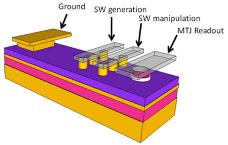
Magnonics [1],[2],[3],[4] is an emerging, and rapidly growing, research field, positioned at the intersection of magnetism, spintronics and electronics, and dealing, in a broad sense, with magnetic phenomena connected with spin waves (SWs). SWs are the dynamic eigenmodes of magnetically ordered materials and represent a phase-coherent collective precession of the local moments [5] and can be considered the magnetic analogue of sound and light waves. Magnonics is therefore to SWs what Photonics is to light. Spin transfer torque (STT) has recently been used to drive the excitation of SWs and is the very mechanism behind nano-contact Spin Torque Nano-Oscillator operation. To the right is shown a possible future magnonic device where a line of three nano-contact STNOs are used for SW generation and an additional line of nano-contacts are used to modulate or modify the propagation of the SWs. Finally, a magnetic tunnel junction (MTJ) is used for read-out of the SWs.
[1] V. V. Kruglyak and A. N. J. Kuchko, J. Magn. Magn. Mater. 272, 302 (2004)
[2] V. V. Kruglyak and R. J. Hicken, J. Magn. Magn. Mater. 306, 191 (2006)
[3] S. Neusser and D. Grundler, Adv. Mater. 21, 2927 (2009)
[4] V. V. Kruglyak, S. O. Demokritov and D. Grundler, J. Phys. D: Appl. Phys. 43, 264001 (2010)
[5] A. G. Gurevich and G. A. Melkov,1996 Magnetization Oscillations and Waves (New York: Chemical Rubber Corp.)
Magnetoplasmonics
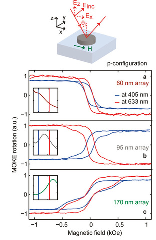
Magnetoplasmonics [1-3] combines both magnetic and plasmonic functionalities where the EM field enhancement associated with various plasmon resonances can significantly alter the magneto-optical activity. Concurrently, the plasmonic properties can be controlled by an external magnetic field, allowing for novel telecommunications and biosensing applications.
[1] G. Armelles, et al., Adv. Optical Mater., 1, 10 (2013)
[2] V. Bonanni, et al., Nano Lett., 11, 5333 (2011).
[3] J. Chen, et al., Small, 7, 2265 (2011).
[1] G. Armelles, et al., Adv. Optical Mater., 1, 10 (2013)
[2] V. Bonanni, et al., Nano Lett., 11, 5333 (2011).
[3] J. Chen, et al., Small, 7, 2265 (2011).
Graded Anisotropy
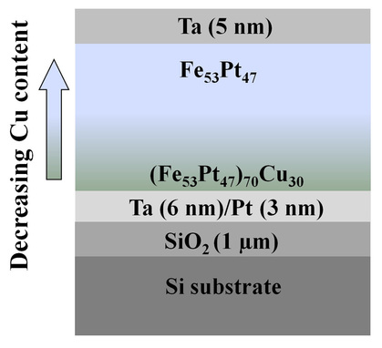
Graded anisotropy (Ku) [1] materials are one possible solution to the magnetic recording “trilemma” where the thermal stability, writability, and signal-to-noise ratio must be simultaneously balanced for successful long-term storage. In graded-Ku materials the low-Ku layers act to reduce the writing field while the high-Ku layers preserve thermal stability. The approach primarily pursued by our group [2] relies on the fabrication of continuously graded FePtCu single films where we take advantage of the strong dependence of the low-Ku A1 phase to the high-Ku L10 ordering temperature in compositionally graded (Fe53Pt47)100−xCux ( x=0–30). The Ku-gradient is then established after proper post-annealing. In addition to conventional magnetometry, subsequent characterization is then carried out using the magneto-optical Kerr effect (MOKE) [3], first-order reversal curves (FORCs) [4], and polarized neutron reflectivity (PNR) [5].
[1] D. Suess, Appl. Phys. Lett. 89, 113105 (2006).
[2] C. L. Zha, et al., Appl. Phys. Lett. 97, 182504 (2010).
[3] V. Bonanni, et al., Appl. Phys. Lett. 97, 202501 (2010).
[4] R.K. Dumas et al., IEEE Trans. Magn. 47, 1580 (2011).
[5] R. K. Dumas, et al., Phys. Rev. B 84, 054434 (2011).
[1] D. Suess, Appl. Phys. Lett. 89, 113105 (2006).
[2] C. L. Zha, et al., Appl. Phys. Lett. 97, 182504 (2010).
[3] V. Bonanni, et al., Appl. Phys. Lett. 97, 202501 (2010).
[4] R.K. Dumas et al., IEEE Trans. Magn. 47, 1580 (2011).
[5] R. K. Dumas, et al., Phys. Rev. B 84, 054434 (2011).
Tilted Anisotropy
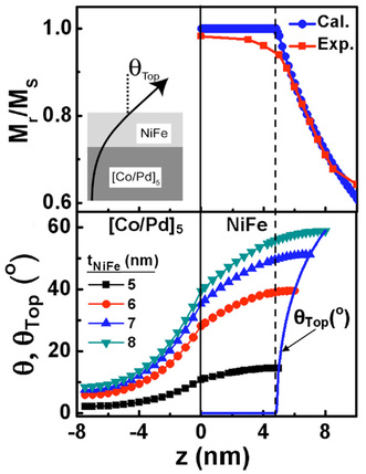
The use of a spin polarizing layer with a tilted magnetization [1-3] for use in spin torque oscillators has been recently proposed. Here, the fixed layer magnetization is tilted out of the film plane in order to simultaneously achieve zero-field operation without the need for additional read out layers and high output power [4]. Varying the tilt angle introduces an additional degree of freedom and leads to a rich phase diagram of spin transfer torque switching and precession [5]. Our approach relies on taking advantage of the competition between materials with distinct anisotropy directions. For example, by exchange coupling a NiFe layer with dominant in-plane shape anisotropy with a [Co/Pd] multilayer with perpendicular anisotropy a highly tunable range of tilt angles can be achieved.
[1] T. N. Anh Nguyen, et al., Appl. Phys. Lett. 98, 172502 (2011).
[2] T. N. Anh Nguyen, et al., J. Magn. Magn. Mat. 324, 3929 (2012).
[3] S. Chung, et al., J. Phys. D: Appl. Phys. 46, 125004 (2013).
[4] Y. Zhou, et al., Appl. Phys. Lett. 92, 262508 (2008).
[5] Y. Zhou, et al., New J. Phys. 11, 103028 (2009).